WaterFuel
Hyundai Motor Co. announced Tuesday that it has become
the first company to begin mass production of a hydrogen
fuel cell-powered vehicle, with a goal of having the
first cars hit European streets early next month.
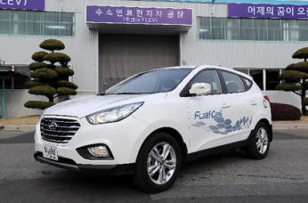 The
company plans to lease 15 of its ix35 vehicles to the
Municipality of Copenhagen, Denmark, over the next few
months and wants to get 1,000 of its vehicles on the
road by 2015. Those vehicles will be leased to private
companies and governments. Hyundai hopes to start
selling the car to consumers sometime in 2015.
The
company plans to lease 15 of its ix35 vehicles to the
Municipality of Copenhagen, Denmark, over the next few
months and wants to get 1,000 of its vehicles on the
road by 2015. Those vehicles will be leased to private
companies and governments. Hyundai hopes to start
selling the car to consumers sometime in 2015.
Frank Ahrens, vice president of global corporate
communications with the company, says the rollout is
starting in Europe because they have a better hydrogen
gas station infrastructure in place. With prices per
vehicle in the "upper $100,000s per car," the ix35—which
emits only water vapor as its exhaust—is too expensive
for general consumers right now, he says. The company
hopes to bring the price of hydrogen cell cars down to
about $50,000 by the time they're ready to sell to
consumers.
"Is this the ultimate car of the future, we don't know,
but we think it'll be one of them," he says. "We think
it's time to get these out on the road and in front of
people's faces."
Fuel cell vehicles use hydrogen gas combined with oxygen
from the environment to create electricity in what is
known as the fuel cell stack, which then powers a quiet
electric motor. The only waste product is water vapor or
a few water droplets. The Department of Energy notes
that fuel cell vehicles "have the potential to
significantly reduce our dependence on foreign oil and
lower harmful emissions that contribute to climate
change."
Hyundai has been developing its hydrogen fuel cell
technology since 1998, but until recently cars powered
by the technology would have cost more than $1 million.
Experts say the long-promised technology could one day
replace internal combustion engines, but public concerns
about safety and government indecision about which
alternative fuel vehicle would be most appropriate for
the U.S. market have slowed things down.
"Battery makers and fuel cell makers have faced a
challenge where every two years the media or the
government switches the flavor the month. First it was
batteries, then fuel cells, then it was ethanol," says
David Friedman, deputy director of the Union of
Concerned Scientists' Clean Vehicles Program. "That
created a lot of market uncertainty for
companies—funding has gone up and down as public
perceptions have gone up and down."
Hyundai's vehicle can be refueled in about the same
amount of time as it takes to refuel a gasoline car, has
a top speed of 100 miles per hour, goes from 0-60 mph in
12.5 seconds, and can travel 365 miles on a single tank
of gas.
Hydrogen gas can be created in a number of ways—some of
which use carbon emissions at the point of creation. The
cheapest and, according to Ahrens, "least attractive"
environmentally is reforming natural gas to create
hydrogen gas, which has a "higher carbon output than
anyone would like." Others are working on creating
hydrogen fuel by electrifying water, and in California
people are experimenting with extracting hydrogen from
human waste as water treatment plants.
"It doesn't take a lot of money to make a new hydrogen
station," he says. "We're releasing these in Europe
because they have a hydrogen roadmap—[the United States]
has to have the will to do it."